
Carrier Model Fe4anf005000aaaa Wiring Diagram
Carrier 38AH024-034 Installation, Start-Up And Service Instructions Manual.pdf 2Mb Download. Carrier 38AKS013-024 Wiring Diagrams.pdf 438.9kb Download. Carrier 38AW050H7 Service Manual.pdf 3.5Mb Download. Carrier 38BK-009 Owner's Manual.pdf

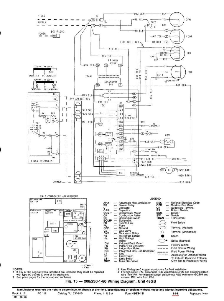
Carrier 48SS018060, 48SX024060 Fig. 30 208/230160 Wiring Diagram
Wiring Diagrams INDEX UNIT 50BYN V-PH-Hz LABEL DIAGRAM FIG. NUMBER 006 008 208/230-3-60 460-3-60 11720011-C 1 575-3-60 012 208/230-3-60 014 460-3-60 11720960-B 2. CarrierTEMPThermostat— The Carrier TEMPSys-tem is a control system which includes a relay pack, TEMP system thermostat, sensors and appropriate wiring.The TEMP.

Carrier Heater Wiring Diagram Manual EBooks Carrier Wiring Diagram
CA14NA Wiring Diagrams Split System Air Conditioner with Puron Refrigerant 1---1/2 To 5 Nominal Tons Fig. 1 - Wiring Diagram — Model sizes 1--1/2 -- 5 tons, 208/230--1

dpst relay wiring
INTRODUCTION. FB4C and FX4D models are R−410A Fan Coils designed for installation flexibility. These units leave the factory compliant with low leak requirements of less than 2% cabinet leakage rate at 0.5 inches W.C. and 1.4% cabinet leakage rate at 0.5 inches W.C. when tested in accordance with ASHRAE 193 standard.

Carrier 38en015300 Wiring Diagram
Incoming wire size range of non-fused disconnect with Minimum Circuit Amps (MCA) up to 599.9 amps is 3/0 to 500 kcmil. Incoming wire size range of non-fused disconnect with MCA from 600 to 799.9 amps is 1/0 to 500 kcmil. Incoming wire size range of non-fused disconnect with MCA from 800 to 1199.9 amps is 250 to 500 kcmil.

Carrier Infinity Thermostat Wiring Diagram Free Wiring Diagram
Wiring Diagrams 25HBC5 Comfort™ 15 Heat Pump with Puronr Refrigerant 1---1/2 to 5 Nominal Tons Fig. 1 - Wiring Diagram — 25HBC518--60, 208/230--1
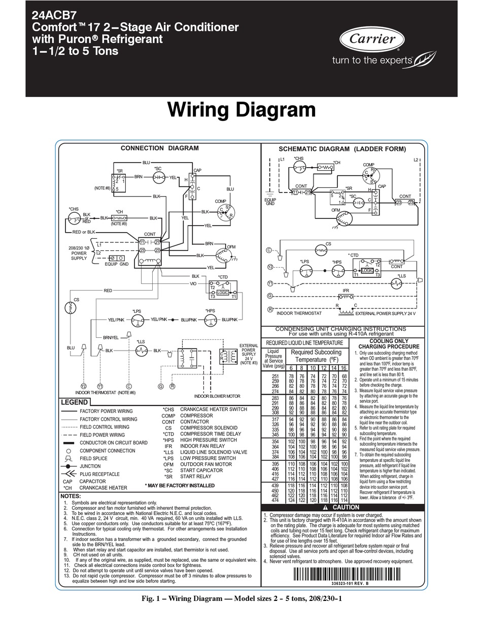
CARRIER 24ACB7 COMFORT WIRING DIAGRAM Pdf Download ManualsLib
Check to make sure wiring diagrams and schematics are present and legible. Replace if missing or damaged. e. Inspect for damage and check tightness on all wire harnesses and connections using a Pozi drive (star) screwdriver. f. All instructional labels and placards should be in place and legible. Refer to Figure 21.
Carrier Model Number 24vna937a300 Wiring Diagram
The FB4C(S,Q)L018-060 size fan coils come equipped with a bleed port style, adjustable R-410A thermal expansion valve (TXV). The valve incorporates a 15% bleed port to ensure equalization during the off cycle and prevent compressor hard starts. The valve is also fully adjustable if this function is needed.
Carrier 58tua Wiring Diagram
Page 5 VOLTAGE PCB BLOCK WIRING FUSE TIME DELAY FUSE LR40061 FAN RELAY A97020 Fig. 3A—Fan Coil Printed-Circuit Board 3. Check field power leads L1 and L2. If these are not receiving 2. Check sequencer/relay number 1 and plug wiring. Yellow power, system cannot function. wire should be connected to pin number 9 of plug and to limit switch.

Carrier Heat Pump Wiring Diagram Thermostat Free Wiring Diagram
CARRIER FAN COIL ACCESSORY ELECTRIC HEATERS WIRING DIAGRAMS [PDF] - All Models, (2013) Carrier Corporation, CAC / BDP D 7310 W. Morris St., Indianapolis, IN 46231 USA Catalog No: WD - FANCOIL - 02 Carrier FFD DIRECT EPANSION FAN COIL UNIT INSTALLATION INSTRUCTIONS FF1D [PDF] (2002)
Carrier Wiring Diagram.
Insert heater assembly into front of fan coil so that element rods engage holes in rear heat shield. Attach heater control plate to fan coil using 2 screws provided. For 18-, 24-, and 30-kw heater models, attach front of heater to fan deck using third screw. (See Fig. 1.)

Carrier Ac Wiring Diagram Free Wiring Diagram
MOTOR SYSTEM TRANSFORMER: 40.0VA FAN COIL: 4.0 VA REMAINING VA AVAILABLE: 36.0 VA. Use Copper Wire (75oC Min) Only Between Disconnect Switch And Unit. To Be Wired In Accordance With N.E.C. And Local Codes. If Any Of The Original Wire, As Supplied, Must Be Replaced, Use The Same Or Equivalent Type Wire.

Carrier Unit Wiring Diagram » Wiring Core
2. Use 75° C min wire for field power supply, use copper wires for all units. 3. All circuit breakers "Must Trip Amps" are equal to or less than 156% RLA. 4. Compressor and fan motors are thermally protected — three phase motors protected against primary single phase conditions. 5. Red jumper wire must be added between R and WI for Space.

Carrier 26542 Wiring Diagram
Wiring Diagram 24VNA9 Infinityr 19VS Variable Speed Air Conditioner with Puronr Refrigerant Fig. 1 - 24VNA9 208/230--1
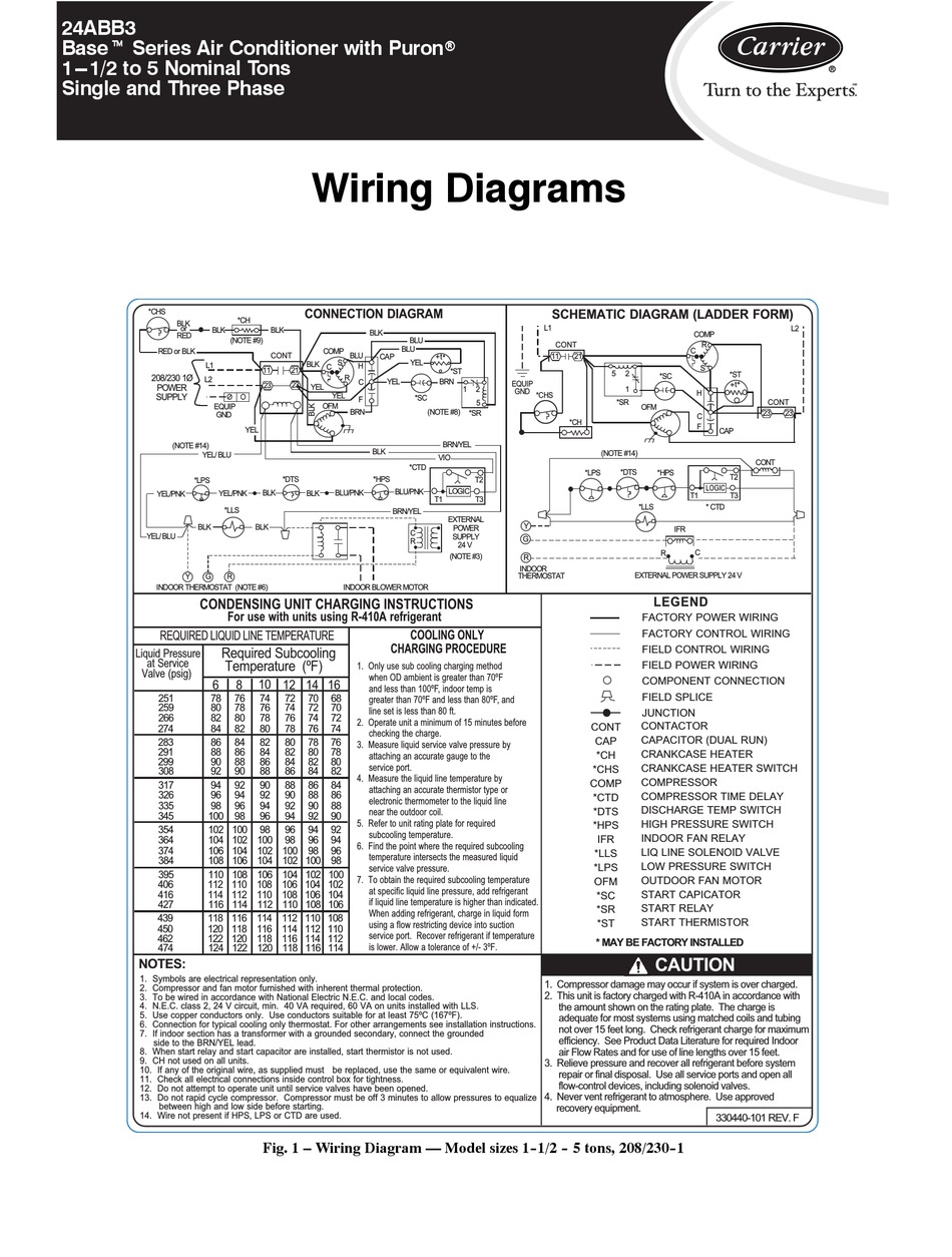
CARRIER BASE SERIES WIRING DIAGRAMS Pdf Download ManualsLib
1.1.2 How the ComfortPro Operates The ComfortPro has two modes of operation: manual and automatic. Manual Mode You start the APU from within the truck bunk using the On/Off button on the driver control panel (DCP). Once the APU is running, you can start and stop the fan, heater and air conditioning using the DCP.

Carrier Ac Wiring Diagram Manual EBooks Carrier Wiring Diagram
Fig. 2 - Wiring Diagram — Model size 2--1/2 -- 5 tons, 208/230--3 and Model size 3 -- 5 tons, 460/3. 3 NOTES: 1. Symbols are electrical representation only. 2. Compressor and fan motor furnished with inherent thermal protection. 3. To be wired in accordance with National Electric